Table of Contents
DC Motor Controllers
To drive motors using a microprocessor requires converting low-power digital logic into high current voltage signals to actual motors. Usually some kind of intermediate chip or circuit is required to do that, especially if the motor should turn in both directions. There are three chips that we've worked with. They are: half h-bridges, full h-bridges, motor controllers/drivers, and RC-PPM servomotor controllers.
Full H-Bridge
To be written.
Half H-Bridges
To be written.
Motor Controllers/Drivers
These implement a lot of the circuit components associated to H-Bridges and abstract away the details so that you can focus on just supplying the two most important signals, direction and speed. Examples include the Sabertooth series (from the2x5 to the 2x60), as well as the possibly newer line http://www.dimensionengineering.com/products/syren10}SyRen XX of regenerative motor drivers.
RC-PPM Servomotor Controllers
The most popular, according to our experience, of RC-PPM servomotor controllers are the Sabertooth models (e.g., the 2-5 and the 2-12 RC models. They take as input RC servomotor PPM signals and output the right kind of PWM signal needed to drive a motor at a turn rate based on the given PPM signal.
In February 2016, our team was asked to debug two PCBs that were created after the original Senior Design team project. The PCBs were modeled after the on-breadboard control circuit that the Senior Design group used, but they had not been checked out and so it was unknown if either PCB was operational. One board was already populated with resistors and chips, while the other was not.
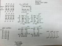
After populating the second PCB, we successfully verified that - based on the pathways between the inputs, chips, and outputs - both of them should work fully as expected. We also mapped out the full schematic of the board, seen here:
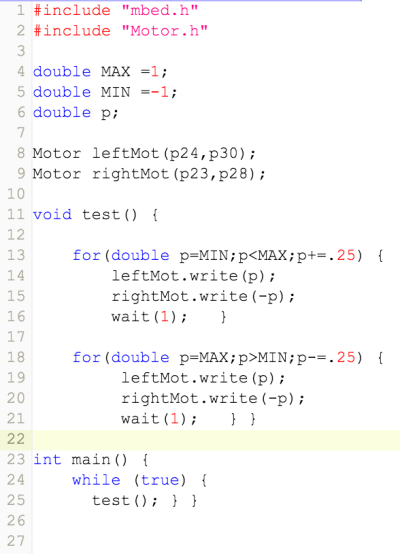
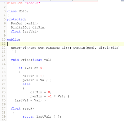
Next, we wanted to actually verify that the PCBs function as expected. To accomplish this, we wrote mBed code that output a Pwm signal from one pin and a directional bit from another pin. To make this easier, Professor Vela wrote a Motor class for us. The full code, the Motor class, and the video of the output is shown below:
https://www.youtube.com/watch?v=QmQk5QXU7EY
The heart of the PCBs are the half-h driver chips (SN754410 Quad Half-H). These chips allow a motor to be driven forward or backward depending on the state of the directional bit (if it's 1, forward; 0, backward).
To clarify this, each output of the half-h drivers lead directly to one of the eight pins seen on the bottom right side of the PCBs. A motor is connected to a horizontal pair of pins, allowing four unique motor connections in total. Due to the functionality of the half-h driver (assuming the code is written correctly), one of the pins will be ground while the other delivers the desired Pwm signal to the motor.
In the case of the code and the video shown above, the motor begins going full speed forward, slows down, stops, then accelerates backwards, slows down, stops, accelerates forward, and repeats.
If one pin was compared to a constant ground, it would only be active half of this cycle time.
The boards also have six servo hookups that are ready to be used. While we did map out which mBed Pwm pin they each relate to, we did not physically test them with a servo of our own.


