Table of Contents
Lynx6 Calibration
The manipulator setup function is called piktul_calibrate and is what you should invoke to first get acquainted with the manipulator.
The idea behind calibration is that the servo commands go from 500 to 2500, but as a user you'd like to be able to enter joint commands in more sensible units (like degrees or inches). Therefore a linear mapping is needed to go between the desired joint configuration (in degrees or inches) and the actual servo commands. The way it is done in the GUI is to create a mapping between three joint coordinate values and the corresponding three servo commands. There is then Matlab code that does the linear interpolation. The three values that will be selected should be the extremal values plus the center value. For a revolute joint, that would be the largest and smallest reasonable angles that are achievable plus some angle in between. For the most part, this will involve +/-90 and 0 degrees.
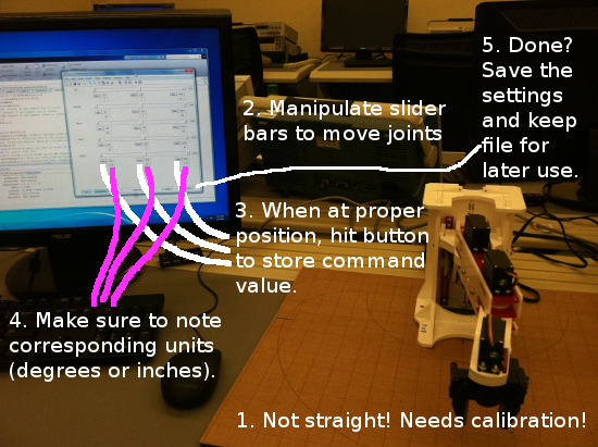
A summary of the procedure is packed into the following image. Use it as a guide when reading through the rest of the calibration page.
Starting
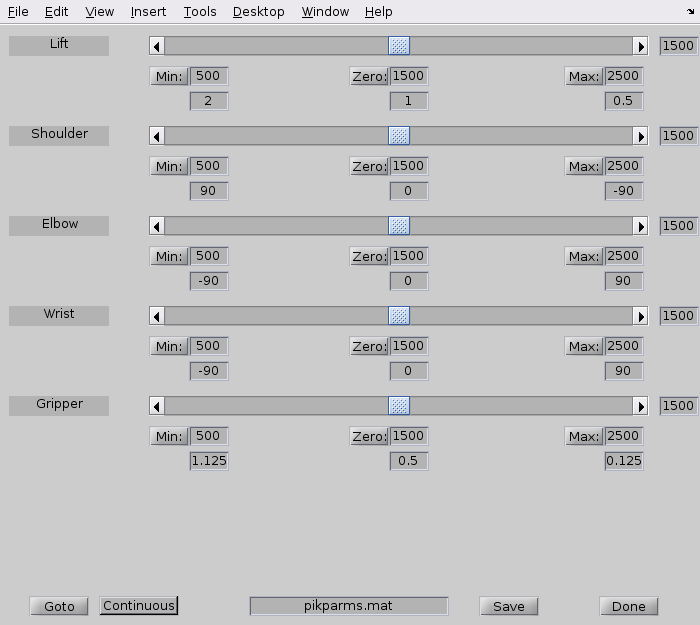
This function pops open a GUI that has sliders bars to control the manipulator servo motors (depicted below). The servo motors are sent numerical commands that range in [500, 2500], where 500 specifies one extreme of rotation and 2500 represents the other extreme. The servo should be centered around 1500. Hence the setup function starts off with all settings at 1500. The manipulator should be plugged, powered-up, and connected to the computer via the serial cable prior to running the setup function. This is because the manipulator will be repeatedly sent the command to go to 1500 for all servos in order to activate the servo motors. If the servos do not activate, then hit the Goto button repeatedly until it does so (if this still fails, come see me).
Considering the image of the calibration GUI above, there are several editable text fields and well as some push-buttons. On the left is the description of the function performed by the joint variable (top is the first, bottom is the last, here fifth). The slide bar to the right of each description selects the servo command from within the [min, max] range. The current selection is to the right of the slider bar. Below each slider bar there are two text boxes, one for the servo command and one for the corresponding joint coordinate value.
Even though it is possible to edit the text boxes for the RC servo commands, you can also use the push buttons next to the text box. Basically, once the arm is at the desired minimum value for a given joint coordinate, then hitting the Min button will copy the current servo command into the text box and lock it in. The slider bar may adjust its range also, so you might see the bar location move a bit.
The numerical limits are 500 and 2500, but some may be set conservatively within these limits to protect the servos. If you hit the max and you think that the servo can go more, then adjust the min/max values and move into these new limits slowly. The min and max are editable text boxes.
Only if you build the manipulator It is critical that those who have built the manipulator remove the gripper servo motor from the gripper and have it sitting off to the side prior to invoking the setup function (do NOT lose the screw). Please still have it be connected to the servo controller board, just not engaged in the gripper. If the servo is in the gripper when it starts up and the servo was improperly installed, then activation could destroy the servo. Once the servo is activated, you can put it back into the gripper making sure that the gripper itself is at the half-way position when the servo motor is installed.
The Setup Function: Sliders
Once the manipulator is powered-up and the servos are (safely) activated, then you can slide the bars around to test out the motion limits. You must hit Goto every time you change the slider, if you want the manipulator to actually move. Enabling the Continuous button will continuously update the manipulator after changing a slider bar.
Usually, the idea is to go joint by joint figuring out the limits. Once a joint and its mapping has been figured out recentering it and map out the next joint.
The Setup Function: Limits
When you adjust the slider bars to identify the limits, please be careful. The servos are dumb things that do what they are asked to do, even if it is incorrect or could break the manipulator. You will know you have done something wrong when a servo starting to make a nasty grinding sound. If you are close to doing something bad, the servo will start to whine louder, with the whine resembling a grinding noise as you get closer to the badness.
Figure out what the servo command values are the get close to the limits, but do not hit them. When doing this, please move the slider bar little by little until you get a feel for the appropriate limits. Also make sure that the manipulator can move freely without hitting anything during this procedure. The associated angles, as measured by a protractor relative to the zero configuration, are the joint angle limits for your manipulator. Each manipulator has different limits based on how it was put together.
Done Calibrating: Deliverable
Once all of the values are set and updated to reflect what works for the Piktul manipulator, take a screen capture of the calibration dialog box. Turn that in as evidence of calibration. Next week, the lab assignment will be to confirm that the calibration is correct by comparing with the forward kinematics. That will be the true test.
Also, turn in what values were used for the sleep joint configuration.
Manipulator Interface Code: Calibration File
The easiest way to have the piktul know what the calibration values should be is to have saved it as a Matlab file for passing to the piktul object. It is one of the optional arguments. Sending the name of the calibration means that the piktul object will load those Matlab variables and overwrite the default values with those from the file. Of course, you will still have to modify the code for the sleep joint configuration. The rest should be automatic. Since the piktul was built here in house and only one version exists, the coded link lengths should be correct.
Once you have the calibration file, the piktul interface can be initialized with the parameters by loading and passing them as the argument to the piktul constructor:
arm = piktul(load('pikparms.mat'));
Manipulator Interface Code: Calibration
The piktul.m code stub is the main interface file for the manipulator. It is what you will be modifying to enhance the functionality of the manipulator as the course progresses. Prior to running the code, you will need to use the setup program to identify the operational limits and calibrate the manipulator. Calibration involves joint angle operational limits (in servo command units and degrees) plus link length measurement. Once these values have been found, the appropriate variables in piktul.m will need to be modified to reflect what you have found. Note: If you used the piktul_calibrate routine, then you do not need to be manually editing the fields here.
Below are some of the variables you'll need to modify. If you have any questions, feel free to ask. Again, please be careful when changing and modifying the values. Be prepared to turn the manipulator off if things go funny.
- alphaOrient: Changes the direction of motion in order to agree with the right-hand rule. Increasing values of joint angle should move in right-hand rule direction based on axis of rotation. If your manipulator is following a left-hand rule, then the sign here should be flipped.
- alphaLims: The joint angle limits you've discovered, or have determined to be the most appropriate for your manipulator. Note that for the last joint, which is the gripper, the units will be in inches (the gripper open width).
- musecLims: The actual servo signals that specify your limits. You may not want to include the full range, but enough to get angles that make sense. You know like a range of [-90, 90] or [-45, 135] and the like.
- alphaHome: Your home position as a joint configuration. I would like for your home position to be the straigh-up position.
- alphaSleep: Your sleep position as a joint configuration.


