This is an old revision of the document!
Optoisolators and Dual Supply Circuit Logic
Often, it is the case that one is running digital logic off of a low power device with its own power supply, and must connect to another digital circuit with its own power supply. The naive approach would be to connect the two grounds together, but that is actually a mistake. Since voltage is a potential measurement (i.e., it is a difference between the high and low leads), there is no guarantee that the two low leads are actually at the same voltage levels. If they aren't, then a ground loop is created. For digital systems, the leaking current associated to a ground loop and the resulting fluctuations that may occur lead to ground bounce, whereby the digital logic behaves erratically. The simplest mechanism to avoid these problems is to preserve the electrically decoupled structure of the two original circuits through an opto-isolator or opto-coupler (the wiki link has a good description and nice circuit drawing). It also plays the additional role of protecting the circuit from weird current spikes should that be a potential issue on one of the two supply sides. Let's say, like when you are connecting a low-voltage, low-power embedded controller to a high-voltage, high-current motor drive system.
Explanation
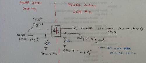
As noted above, Wikipedia has a good explanation. This here is the quick and dirty version, which uses the image below as a reference.
Quick and dirty sketch of opto-isolator circuit for bridging logic of two two power supplies.
To protect the mBed from the necessary external power supplies, we used an optoisolator (MCT6) chip to bridge them. An optoisolator is basically a relay that uses photodiodes instead of mechanical contacts to switch back and forth.
We needed one because the 3.3V regulated Vout was not enough to control a servo motor, which requires 4-6V. In addition, the 5.0V USB out cannot function at the same time as the mBed. Either you are controlling your electronics with the mBed or powering them with 5.0V. This is not ideal.
We found this MCT6 datasheet to be helpful. The MCT6 chip contains 2 optoisolators. Here is how to connect the first one: 1. Connect your output wire from the mBed to pin 1. 2. Connect pin 2 to mBed ground with a small valued (1k) resistor. 3. Connect pin 7 to external DC ground with a large resistor (10k). 4. Connect pin 8 to external DC Vcc and to the input signal wire of whatever you need to control.
Figure 1: The MCT6 optoisolators used in a circuit.


