Table of Contents
Optoisolators and Dual Supply Circuit Logic
Often, it is the case that one is running digital logic off of a low power device with its own power supply, and must connect to another digital circuit with its own power supply. The naive approach would be to connect the two grounds together, but that is actually a mistake. Since voltage is a potential measurement (i.e., it is a difference between the high and low leads), there is no guarantee that the two low leads are actually at the same voltage levels. If they aren't, then a ground loop is created. For digital systems, the leaking current associated to a ground loop and the resulting fluctuations that may occur lead to ground bounce, whereby the digital logic behaves erratically. The simplest mechanism to avoid these problems is to preserve the electrically decoupled structure of the two original circuits through an opto-isolator or opto-coupler (the wiki link has a good description and nice circuit drawing). It also plays the additional role of protecting the circuit from weird current spikes should that be a potential issue on one of the two supply sides. Let's say, like when you are connecting a low-voltage, low-power embedded controller to a high-voltage, high-current motor drive system.
Some summarize the role of an opto-isolator by comparing it to a relay, just that it uses photodiodes instead of mechanical contacts to switch back and forth. That's effectively how they are used. Doing so requires setting up the circuit properly.
Explanation
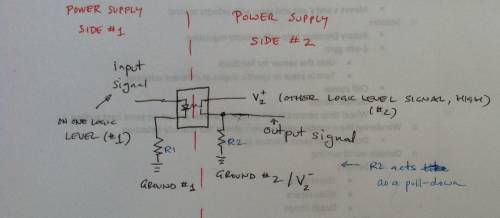
As noted above, Wikipedia has a good explanation. This here is the quick and dirty version, which uses the image below as a reference. to the left of the red dotted line is one supply side, while to the right is the other. Internal to the package there is a small LED for the supply side. When the signal is logic high, the LED turns on and illuminates the sensor on the other side of the package. That sensor acts like a transistor. In the off mode, the gate is open, but in the on mode the gate closes letting current flow on the right hand side. the light sourced by the LED is what provides the activation current for the gate to close since the gate is optically driven.
Quick and dirty sketch of opto-isolator circuit for bridging logic of two two power supplies.
To duplicate the digital logic of the left side, the main idea is to tap off of the second pin with a pull-down. In the off mode, the pull down ensures logic low. In the on mode, the system will become logic high. Since the gate has some low resistance, the right hand side circuit will behave like a resistor-based voltage divider, so it won't be pure logic high but something slightly lower. How low depends on the value of R2. What's important is for the high to be high enough to trigger the digital logic of the other side.
Since the gate has some nominal level of inductance too, the left-hand and right-hand side circuits will behave like a first-order stable feedback system. They will have a rise-time and steady-state error that will depend on the resistor values chosen. These properties will influence the maximum frequency that the opto-isolator can reproduce in digital form. In effect, there is a maximum frequency that the input digital logic can operate at. For things in the KHz range, it is usually not a problem. Using a standard opto-isolator for I2C or SPI operation at MHz rates doesn't really work. Instead, specialized high-speed chips are needed, usually designed for specific communication application.
mBed Implementation for RC Servomotors
In this example, an opto-isolator is needed because the mBed uses 3.3V as the logic and also does not provide the current needed to drive a motor. The servomotor here is an RC servomotor which uses a supply in the 4-6V range. Normally, we use a P2501 opt-isolator, however in this case the students used a different chip, the MCT6.
We found this MCT6 datasheet to be helpful. The MCT6 chip contains 2 optoisolators. Here is how to connect the first one:
- Connect your output wire from the mBed to pin 1.
- Connect pin 2 to mBed ground with a small valued (1k) resistor.
- Connect pin 7 to external DC ground with a large resistor (10k).
- Connect pin 8 to external DC Vcc and to the input signal wire of whatever you need to control.
In this described configuration, the right hand side appears to be operating in pull-up mode.
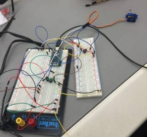
Figure 1: The MCT6 optoisolators used in a circuit.
The image is a bit messy due to the wires being everywhere, but it should be somewhat clear that the second, smaller proto-board has an opto-isolator on it. It is acting as the bridge between the mBed side and the RC servomotor side. The blue wire at pin 8 of the MCT6 ultimately connects to the second (signal) pin of the servomotor. The first and third (right-most) wires and pins are the power and ground. It looks to be that the third pin is ground.

